CSE 120 Study Guide - Final Guide: Block Diagram, Embedded System, Circuit Diagram

15 Sep 2018
School
Department
Course
Professor
Document Summary
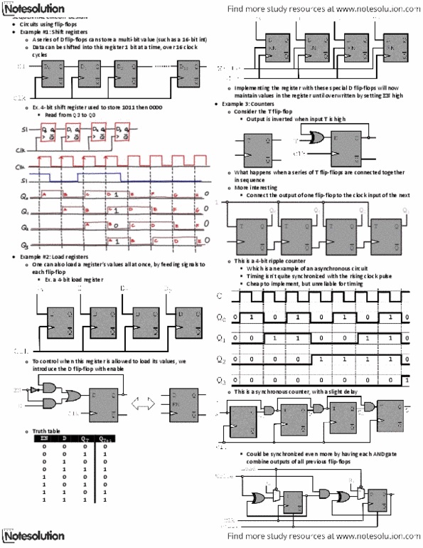
Fundamental to the synthesis of sequential circuits is the concept of internal states. At the start of a design the total number of states required are determined. This is achieved by drawing a state diagram, which shows the internal states and the transitions between them. All states are stable (steady) and transitions from one state to another are caused by input (or clock) pulses. Each internal state is represented in the state diagram by a circle containing an arbitrary number or letter; transitions are shown by arrows labelled with the particular input causing the change of state. In the case of pulse outputs the transition arrows are also labeled with the output associated with the input pulse. This will be made clear by examples given below. The state table representation of a sequential circuit consists of three sections: labelled present state: next state, output. The present state designates the state of flip-flops before the occurrence of a clock pulse.