ENGR2000 Lecture Notes - Lecture 5: A.D. Vision, Continuity Equation, Allis-Chalmers D Series

2 Jul 2018
School
Department
Course
Professor

2nd-Year Fluid Mechanics, Faculty of Science & Engineering, Curtin University
ENGR2000: FLUID MECHANICS
For Second-year Chemical, Petroleum, Civil & Mechanical Engineering
FLUID MECHANICS LECTURE NOTES
CHAPTER 5: APPLICATIONS OF MASS CONSERVATION,
MOMENTUM EQUATION AND BERNOULLI EQUATION
5.1 Introduction
The fundamental principles of fluid behaviour covered in Chapters 3 & 4 are
applied to a number of engineering problems. Unless otherwise stated the
flow will be assumed to be incompressible and inviscid. As a consequence of
these assumptions, the examples that follow only give approximate solutions.
Nevertheless, they yield results that are useful in engineering applications
(orders of magnitude, physical understanding etc.) in situations that would
make solutions of the full (fluid) equations very complicated and, in some
cases, impossible for the present state-of-the-art.
Chapter 5 −Page 1
find more resources at oneclass.com
find more resources at oneclass.com
2nd-Year Fluid Mechanics, Faculty of Science & Engineering, Curtin University
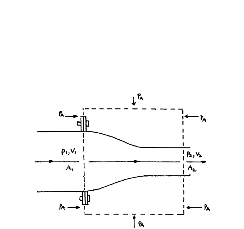
5.2 Example E1: Pipe flow: Force on a nozzle
A pipe of circular cross-section is bolted to a nozzle which feeds into another
pipe of narrower cross-section than the upstream pipe. The joint is held by
a set of flange bolts around the circumference of the bigger pipe. The set-up
is shown in Fig. E1.1.
FIGURE E1.1
Assuming that the flow passes smoothly from upstream to downstream pipes,
find the force which the flange bolts resist in terms of the upstream flow speed,
V1, upstream pressure, p1, and pipe cross-sectional areas, A1and A2.
Solution: Set up a suitable CV as shown in Fig. E1.1 and apply mass
conservation, momentum equation and the Bernoulli equation.
(i) Mass continuity:
V1A1=V2A2(E1.1)
(ii) Momentum equation: (in x-direction)
Chapter 5 −Page 2
find more resources at oneclass.com
find more resources at oneclass.com

2nd-Year Fluid Mechanics, Faculty of Science & Engineering, Curtin University
For steady flow, there is no storage term. Thus:
XF=mom. flux out −mom. flux in
Both pressures and the force, Ff(in the x-direction), of the nozzle wall on
the fluid act. Thus: XF=p1A1−p2A2+Ff(E1.2)
mom. flux in =ρ(V1A1)V1(E1.3a)
mom. flux out =ρ(V2A2)V2=ρ(V1A1)V2(E1.3b)
having used Eqn E1.1 for the second relation above.
Substituting Eqns. E1.2 and E1.3 into the momentum equation and re-
arranging gives:
Ff=ρV1A1(V2−V1)−(p1A1−p2A2) (E1.4)
The force experienced by the walls of the nozzle (and which the bolts must
resist) is −Ff. The equation above solves the problem except that we must
find expressions for V2and p2.V2is found easily from Eqn. E1.1; V2=
(A1/A2)V1. To obtain the downstream pressure use the B.E.
(iii) Bernoulli equation
Applied along a central (horizontal) streamline from upstream to downstream
of the CV. 1
2ρV 2
1+p1=1
2ρV 2
2+p2
so:
p2=p1−1
2ρV 2
1((A1/A2)2−1) (E1.5)
The force on the bolts is thus:
−Ff=−ρA1V2
1((A1/A2)−1)+p1(A1−A2)+ 1
2ρV 2
1A2((A1/A2)2−1) (E1.6)
Note: Have we included all the pressure forces on the CV in Eqn. E1.2?
Chapter 5 −Page 3
find more resources at oneclass.com
find more resources at oneclass.com
Document Summary
For second-year chemical, petroleum, civil & mechanical engineering. The fundamental principles of uid behaviour covered in chapters 3 & 4 are applied to a number of engineering problems. Ow will be assumed to be incompressible and inviscid. As a consequence of these assumptions, the examples that follow only give approximate solutions. Nevertheless, they yield results that are useful in engineering applications (orders of magnitude, physical understanding etc. ) in situations that would make solutions of the full ( uid) equations very complicated and, in some cases, impossible for the present state-of-the-art. 5. 2 example e1: pipe ow: force on a nozzle. A pipe of circular cross-section is bolted to a nozzle which feeds into another pipe of narrower cross-section than the upstream pipe. The joint is held by a set of ange bolts around the circumference of the bigger pipe. Assuming that the ow passes smoothly from upstream to downstream pipes,