ENGR2000 Lecture Notes - Lecture 6: Power Law, Reynolds Number, Flow Velocity

2 Jul 2018
School
Department
Course
Professor
Prepared by Dr Hongwei Wu Chapter 6 – Page 1 of 19
2nd – Year Fluid Mechanics, Faculty of Engineering and Computing, Curtin University
ENGR2000: FLUID MECHANICS
For Second-Year Chemical, Civil and Mechanical Engineering
FLUID MECHANICS LECTURE NOTES
CHAPTER 6 VISCOUS FLOW IN PIPES
6.1 Introduction
In this chapter, we will consider viscous incompressible flow in pipes where the fluid is
confined and bounded. Pipe systems are widely used in practice. Typical examples include
drinking water distribution pipe systems, oil pipe lines etc. Figure 6-1 presents the schematic
diagram of a typical pipe system.
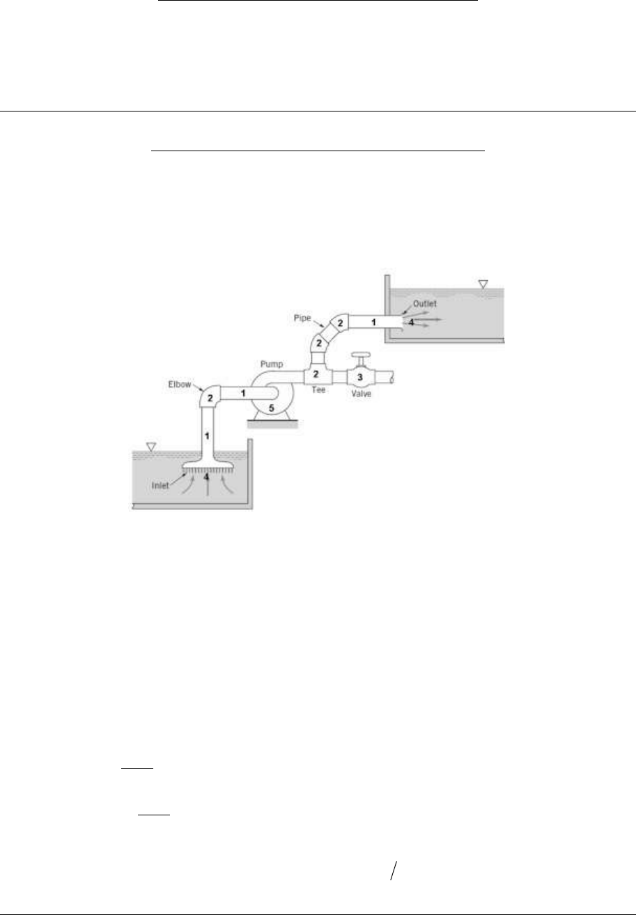
Figure 6-1 A typical pipe system [1]
As shown in Figure 6-1, a pipe system may include
1. Individual straight pipes
2. Pipe connectors (such as Tee-union, elbow connector etc.), for connecting pipes
3. Flow rate control devices (such as valves) for adjusting the flow rate
4. Inlet and outlet
5. Pumps which add energy into the fluid
where items 2, 3 and 4 are often called pipe components.
6.2 Real pipe flow
For inviscid, incompressible, steady and irrotational flows, Bernoulli’s Equation applies
streamlineaalongconst
V
gzP,
2
2
which can also be written as
0)
2
(
2
V
gzP
. (E6-1)
Equation E6-1 indicates that for ideal fluid (
0
), if there is no change in the sum of the
fluid elevation and dynamic pressure, i.e.
0)2()( 2 Vgz
, the overall pressure drop
across a pipe system should be zero.
find more resources at oneclass.com
find more resources at oneclass.com

Prepared by Dr Hongwei Wu Chapter 6 – Page 2 of 19
However, for real fluid, energy loss hence pressure drop
L
P
across a pipe system is
inevitable because of the shear force (friction) between the pipe and the fluid. This friction is
a result of the viscous nature of real fluid (
0
). To deliver the fluid through a pipe system,
pumps are often introduced into the pipe system in order to provide pressure rise
work
P
.
Therefore, E6-1 is no longer applicable to real pipe flows and we need to consider both
L
P
and
work
P
, i.e.
0)
2
(
2
Lwork PP
V
gzP
. (E6-2)
The pressure drop
L
P
can be due to pressure drop in straight pipes (Item 1 in Figure 6-1),
called major loss, and pressure drop in pipe components (Items 2, 3 and 4 in Figure 6-1),
called minor loss. Therefore, we have
orLmajorLL PPP min,,
. (E6-3)
Equation E6-2 shows that to deliver fluid through a pipe system, a pump needs to be properly
selected to provide enough pressure rise to overcome the pressure drop due to friction in the
pipe system, the changes in elevation and the dynamic pressure. It indicates that to design and
operate a real pipe system, we need to have sufficient knowledge on:
1. the relationship among pressure drop across a straight pipe (i.e. major loss), the pipe
properties and flow properties (This is discussed in Chapter 6)
2. the relationship among pressure drop across pipe components (i.e. minor loss), the
properties of the pipe component and flow properties (This is discussed in Chapter 7)
3. the energy gain by devices such as pumps (This is the topic of Chapter 10)
Head forms of E6-1, E6-2 and E6-3
These equations can also be expressed in head forms as the following:
0)
2
(
2
g
V
z
g
P
(E6-1a)
0)
2
(
2
Lwork hh
g
V
z
g
P
(E6-2a)
orLmajorLL hhh min,,
. (E6-3a)
In the head form, each of the terms has the units of length and represents a certain type of
head. For example, the elevation, z, is related to the potential energy and is called elevation
head. The pressure term,
gP
/
, is called static (or pressure) head and represents the
height of a column of the fluid that is needed to produce the pressure, P. The velocity term,
gV 2/
2
, is the dynamic (or velocity) head and represents the vertical distance needed for
the fluid to fall freely if it is to reach velocity V from rest. Similarly, hwork and hL are
termed as pump head and head loss, respectively.
6.3 Pioneer work on measuring pressure drop across a pipe
6.3.1 Pressure-drop test [2]
Figure 6-2 illustrates is a simple experimental setup for measuring pressure drop across a pipe.
Liquid flew from the tank (by elevation energy) to the pipe. There would be a long section
where the flow was not uniform, before the fluid entering the test section to produce a
uniform flow. The test section has a length of
x
and the pressures at both ends were
measured as P1 and P2.
find more resources at oneclass.com
find more resources at oneclass.com

Prepared by Dr Hongwei Wu Chapter 6 – Page 3 of 19
A flow-regulating valve was introduced to control the flow rate so that tests could be
conducted to find the correlation between the pressure gradient across the test section and the
fluid flow rate in pipe. Figure 6-3 presents the original experimental results of Osborne
Reynolds in 1883 of one specific fluid and one specific pipe [3]. Extensive experiments
showed that these observations are generic for pipe flow, regardless of the type of liquid and
kind of pipe used in such experiments.
Figure 6-2 Experimental setup for pressure-drop test [2].
Figure 6-3 Measured pressure gradient
x
P
(i.e.
x
PP
12
) of a specific pipe as a function of
volumetric flow rate Q of a specific fluid [2], originally from reference [3].
find more resources at oneclass.com
find more resources at oneclass.com
Document Summary
2nd year fluid mechanics, faculty of engineering and computing, curtin university. In this chapter, we will consider viscous incompressible flow in pipes where the fluid is confined and bounded. Typical examples include drinking water distribution pipe systems, oil pipe lines etc. Figure 6-1 presents the schematic diagram of a typical pipe system. As shown in figure 6-1, a pipe system may include: individual straight pipes, pipe connectors (such as tee-union, elbow connector etc. ), for connecting pipes: flow rate control devices (such as valves) for adjusting the flow rate, inlet and outlet, pumps which add energy into the fluid where items 2, 3 and 4 are often called pipe components. For inviscid, incompressible, steady and irrotational flows, bernoulli"s equation applies gz. P const along a streamline which can also be written as. 0 ), if there is no change in the sum of the. Equation e6-1 indicates that for ideal fluid ( gz.