Mechatronic Systems Engineering 2201A/B Lecture 4: Circuit Concepts and Diagrams: Resistors, Resistance and Ohm’s Law

15 Sep 2018
School
Department
Professor
Document Summary
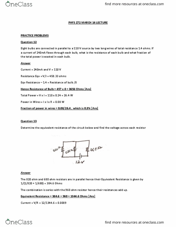
An ideal resistor is a two-terminal electric circuit element that produces a voltage across its terminals that is proportional to the electric current through it. Mathematically, an ideal resistor is described by ohm"s law: Using ohm"s law ( ) to substitute for in , we get. Alternatively, using ohm"s law to substitute for i in , we get. In real life, is always positive resistors absorb energy. Power absorbed by resistances is converted into heat. Example: an electric bulb is rated for 100 w and 120 v. find its resistance and operating current. Example: a 1-k resistor used in a television receiver is rated for a maximum power of 0. 25 w. find the current and voltage when the resistor is operated at maximum power. Several resistances in series can be replaced by one equivalent resistance. Analogously, several resistances in parallels can be replaced by one equivalent resistance.