3
answers
1
watching
333
views

OC4377765Lv1
7 May 2022
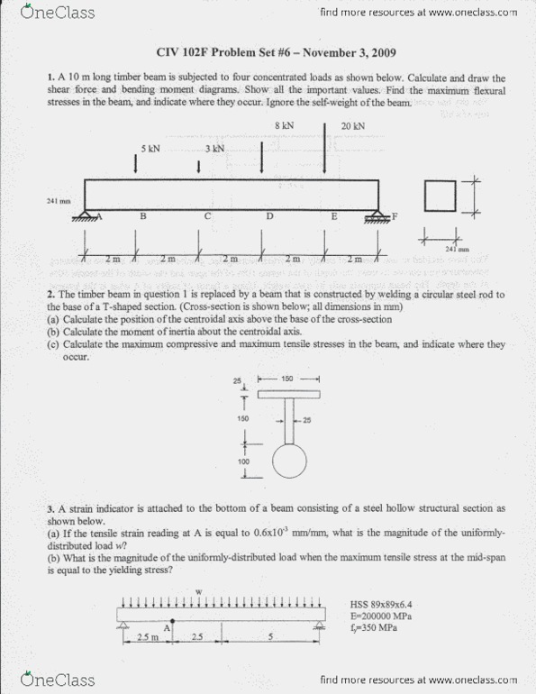
The steel member shown in the figure below has a torque of 90 N.m and an axial load of 9000N
applied to it with one end being fixed. The lengths are L= 500 mm L1=200 , and L2=140
and the diameters are d=50 and D=110
- Calculate the maximum tensile stress along with the location and direction.
- Calculate the maximum compressive stress along with the location and direction.
- Calculate on the cross-section the maximum in-plane shear stress along with the location and direction.
- Also identify the point where absolute maximum shear stress takes place and calculate the same with the direction.

Read by 3 people

Read by 6 people

16 May 2022
Already have an account? Log in
Read by 7 people

10 May 2022
Already have an account? Log in