8.02 Lecture Notes - Lecture 1: Rlc Circuit, Angular Frequency, Propagation Constant

Document Summary
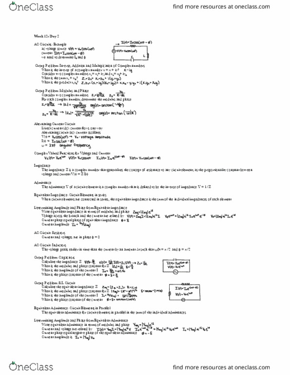
Z = z + z + z = r + i( l - 1/ c) At resonance the voltage across the capacitor is equal in magnitude to the voltage across the induction by phase shifting by 180 . So the two voltage drops sum to zero. The current is exactly in phase with the voltage source: = 0. As i slide the core into the solenoid the light bulb changes brightness. I am driving the circuit though resonance by continuously decreasing the natural frequency of the oscillations in the circuit. In plots that show driving voltage v and current i in a driven rlc circuit, you know which is leading by looking at which curve peaks rst. The circuit shown contains an ac generator, a resistor with resistance r= 1 , and a black box , which contains either an inductor or a capacitor, or both.