CMPSC 64 Lecture Notes - Lecture 14: Sequential Logic, Arithmetic Logic Unit

Document Summary
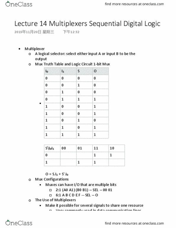
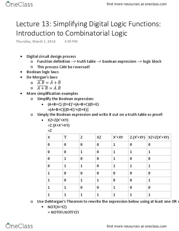
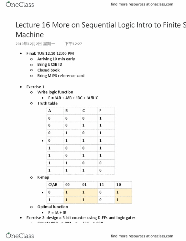
Given the following truth table, draw the resulting logic circuit. Given the following schematic of a circuit, (a) write the function and (b) fill out the truth table: Typically has 3 groups of inputs and 1 output. 1 of the input data lines gets selected to become the output, based on the. If sel = 0, the i0 gets to be the output. If sel = 1, then i1 gets to be the output. The opposite of a mux is called a demultiplexor (demux) Muxes can have i/o that are multiple bits. Muxes can have more than wo data inputs. Makes it possible for several signals (variables) to share one resource. Mux truth table and logic circuit for 1-bit mux. N = how wide the data bus is. M = how many inputs to the mux. The select input (s) has to be able to select 1 out of m inputs. A + b" + 1 = a - b.