CE 5310 Lecture Notes - Lecture 16: Seismic Loading, Angle Of Rotation, Jolla


Cyclic Behavior of Steel Wide-Flange Columns
Subjected to Large Drift
James D. Newell1and Chia-Ming Uang2
Abstract: During an earthquake, steel braced frame columns can be subjected to high axial forces combined with inelastic rotation
demand resulting from story drift. Cyclic testing of nine full-scale W14 column specimens representing a practical range of flange and
web width-to-thickness ratios were subjected to different levels of axial force demand 共35, 55, and 75% of nominal axial yield strength兲
combined with up to 10% story drift. No global buckling was observed in all test specimens. Flange local buckling was the dominant
buckling mode. Specimens achieved interstory drift capacities of 0.07–0.09 rad. These large deformation capacities were, in part, achieved
due to the delay in flange local buckling resulting from the stabilizing effect provided by the stocky column web of the W14 section
specimens. Testing indicated that the ASCE 41 predicted plastic rotation capacities are very conservative. The ASCE 41 criteria do not
specify plastic rotation capacity at axial load ratios greater than 0.5; however, tested specimens exhibited significant plastic rotation
capacities of approximately 15–25 times the member yield rotation.
DOI: 10.1061/共ASCE兲0733-9445共2008兲134:8共1334兲
CE Database subject headings: Beam columns; Cyclic loads; Full-scale tests; Seismic analysis; Seismic design; Steel columns; Steel
frames.
Introduction
Nonlinear time-history analysis of steel braced frames subjected
to earthquake ground motions has revealed that columns in the
bottom stories are often subjected to combined high axial load
and inelastic flexural demand resulting from story drift. Seismic
loading usually results in double-curvature bending in these col-
umns. Analysis results have shown expected story drift ratios of
approximately 2% 共Sabelli 2001兲. This level of drift results in
inelastic rotation demand combined with high axial force demand
in the columns. The reliability of columns under this level of
combined cyclic loading has not previously been experimentally
validated and little guidance is available in codes and standards of
practice.
When more-advanced analysis techniques are employed in de-
sign, plastic rotation angle acceptance criteria for steel moment
frame columns from ASCE 41 共ASCE 2007兲are sometimes used.
The double-curvature bending behavior of moment frame col-
umns is similar to that of braced frame columns where gusset
plates provide beam-to-column connection fixity. According to
ASCE 41, plastic rotation capacity is dependent on axial load
ratio, flange and web width-thickness ratios, and building perfor-
mance objective. The criteria also assume that columns loaded
above one-half their available axial strength are force-controlled
members and possess no plastic rotation capacity.
To provide a basis for performance evaluation of columns
under combined high axial load and drift demand, W14 section
column specimens have been subjected to laboratory and analyti-
cal investigation in this study. A loading sequence for braced
frame column testing was developed and employed for cyclic
testing. Nine steel wide-flange column specimens, representing a
practical range of flange and web width-to-thickness ratios, were
subjected to different levels of axial force demand 共35, 55, and
75% of nominal axial yield strength兲combined with story drift
demand of up to 10% for these simulated bottom-story columns.
The plastic rotation capacity of the specimens was evaluated and
compared with that predicted by ASCE 41.
Loading Sequence Development
The moment frame beam-to-column connection loading history in
AISC 341-05 共AISC 2005a兲is a sequence based on interstory
drift angle. Similarly, the eccentrically braced frame 共EBF兲link-
to-column connection loading history is based on the link rotation
angle. Unlike the moment frame and EBF loading sequences, for
testing of columns under axial load and drift demand a dual-
parameter 共i.e., axial load and story drift兲loading sequence was
required. In this study, development of a braced frame column
loading sequence followed the same basic framework as was used
in development of the steel moment frame beam-to-column con-
nection loading sequence 共Krawinkler et al. 2000兲and EBF
link-to-column connection loading sequence 共Richards and Uang
2006兲.
Three- and seven-story prototype buckling-restrained braced
frame 共BRBF兲buildings 共see Table 1 and Fig. 1兲, designed for a
typical Southern California site, were used for loading sequence
development. The seven-story building was adapted from a
1Graduate Student Researcher, Dept. of Structural Engineering, Univ.
of California, San Diego, La Jolla, CA 92093-0085.
2Professor, Dept. of Structural Engineering, Univ. of California, San
Diego, La Jolla, CA 92093-0085.
Note. Associate Editor: Judy Liu. Discussion open until January 1,
2009. Separate discussions must be submitted for individual papers. To
extend the closing date by one month, a written request must be filed with
the ASCE Managing Editor. The manuscript for this paper was submitted
for review and possible publication on October 11, 2007; approved on
December 27, 2007. This paper is part of the Journal of Structural
Engineering, Vol. 134, No. 8, August 1, 2008. ©ASCE, ISSN 0733-
9445/2008/8-1334–1342/$25.00.
1334 / JOURNAL OF STRUCTURAL ENGINEERING © ASCE / AUGUST 2008
Downloaded 16 Jan 2009 to 129.107.67.17. Redistribution subject to ASCE license or copyright; see http://pubs.asce.org/copyright

design example from Lopez and Sabelli 共2004兲. The three-story
building was designed using plan dimensions and gravity loading
similar to the seven-story building. BRBFs in the north–south
direction 共two braced bays per floor兲were modeled as part of
this study. Models of the three- and seven-story BRBFs were
developed and analyzed with the nonlinear structural analysis
program DRAIN-2DX 共Prakash et al. 1993兲. A suite of 20 large-
magnitude, small-distance Los Angeles ground motion records
were used 共Krawinkler et al. 2003; Medina 2003; Richards and
Uang 2006兲. The design acceleration response spectrum for 5%
damping was adjusted to a 2% damping spectrum using the pro-
cedure of ASCE 41. Scale factors for the earthquake records were
calculated to set the 2% damping spectral acceleration of each
record equal to the 2% damping design spectral acceleration, at
the fundamental natural period of each frame.
Model frames were subjected to each of the 20 specifically
scaled ground motion records. Story drift ratio and column time-
history responses were extracted from the analysis results. For
loading sequence development, story drift ratio time histories
were converted into series of cycles using a simplified rainflow
cycle counting procedure 共Krawinkler et al. 2000; Richards and
Uang 2006兲. These data were then evaluated to develop a loading
sequence that conservatively represented the expected number
and distribution of cycles, maximum and cumulative drift range,
and maximum drift.
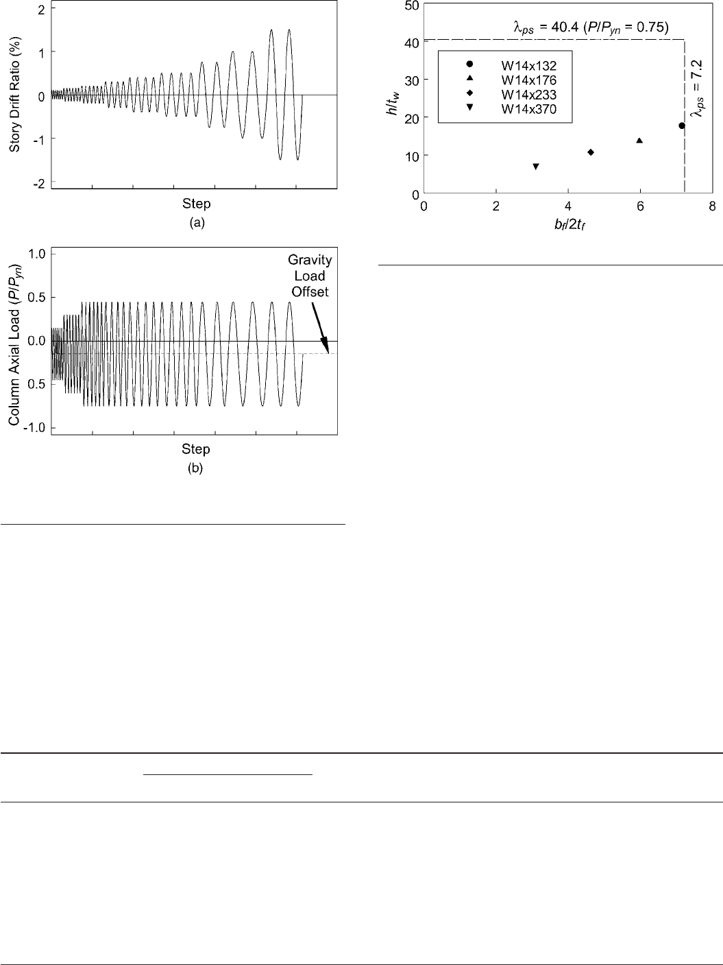
The proposed loading sequence was prescribed in terms of
story drift ratio 共see Table 2兲and target column compressive axial
load. Time-history analysis results showed that bottom-story col-
umn axial load approached a constant maximum value 共average
of 0.24P/Pyn with a standard deviation of 0.008P/Pyn for three-
story BRBF and an average of 0.55P/Pyn with a standard devia-
tion of 0.013P/Pyn for seven-story BRBF兲for all excursions
larger than the yield drift, which was about 0.002 rad. Therefore,
column axial loads for the testing sequence were determined
based on an elastic-perfectly plastic column axial load versus
story drift ratio relationship. Calculation of column axial loads at
the loading sequence drift levels were based on reaching the tar-
get column compressive axial load at 0.002 rad story drift ratio
and axial loads for all excursions larger than the yield drift were
equal to the maximum level for that specimen. The story drift and
column axial load were applied in-phase 共see Fig. 2兲. Note that
the initial step in the experimental sequence was application of
gravity load equal to 0.15Pn.共Bottom-story BRBF column grav-
ity loads of 0.12 and 0.13Pnwere observed for the three- and
seven-story models, respectively.兲Additional details concerning
the braced frame column loading sequence development are re-
ported in Newell and Uang 共2006兲.
Table 1. Member Sizes of Prototype BRBFs
Story Column Beam
BRB Asc
共mm2兲
共a兲Three-story BRBF
1W12⫻96 W12⫻50 4,120
2W12⫻96 W12⫻50 3,310
3W12⫻96 W12⫻50 1,990
共b兲Seven-story BRBF
1W14⫻211 W16⫻50 7,100
2W14⫻211 W16⫻50 6,770
3W14⫻145 W16⫻50 6,130
4W14⫻145 W16⫻50 5,480
5W14⫻74 W16⫻50 4,520
6W14⫻74 W16⫻50 3,550
7W14⫻74 W16⫻50 1,940
Fig. 1. Prototype BRBF buildings: 共a兲plan view; 共b兲three-story
elevation; and 共c兲seven-story elevation
Table 2. Story Drift Ratio Loading Sequence
Load
step
Story
drift ratio
共rad兲
Number
of cycles
0 Apply gravity load Apply gravity load
1 0.001 6
2 0.0015 6
3 0.002 6
4 0.003 4
5 0.004 4
6 0.005 4
7 0.0075 2
8 0.01 2
9 0.015 2
10a0.02 1
aContinue with increments in story drift ratio of 0.01 rad, and perform
one cycle at each step.
JOURNAL OF STRUCTURAL ENGINEERING © ASCE / AUGUST 2008 / 1335
Downloaded 16 Jan 2009 to 129.107.67.17. Redistribution subject to ASCE license or copyright; see http://pubs.asce.org/copyright
Experimental Program
Test Setup and Specimens
The test matrix for the nine specimens is summarized in Table 3.
Column compressive axial load targets of 0.35, 0.55, and 0.75
times the nominal axial yield strength, Pyn, were investigated
combined with up to 10% story drift. Specimens were designated
with the column section size and target axial load, i.e., Specimen
W14⫻132-75 was a W14⫻132 wide-flange section with a com-
pressive axial load target of 0.75Pyn. A total of four sections were
selected such that the effect of width–thickness ratios on cyclic
local buckling behavior could also be investigated. Fig. 3 shows a
comparison of the specimen flange and web width-thickness ra-
tios with the seismically compact limits 共AISC 2005a兲. The tested
W14⫻132 was the smallest W14 section meeting the seismically
compact flange width-thickness ratio limit for A992 steel. All
tested sections were well below the limiting web width–thickness
ratio. Load capacity of the test facility precluded testing of a
W14⫻233 specimen at an axial load of 0.75Pyn and a W14
⫻370 specimen at an axial load of 0.55 or 0.75Pyn.
Testing used the University of California, San Diego, 共UCSD兲
Seismic Response Modification Device 共SRMD兲Test Facility as
shown in Fig. 4. Column specimens were tested in a horizontal
configuration with one end of the specimen attached to a reaction
fixture that was attached to a strongwall. The other end of the
specimen was attached to a reaction fixture attached to the SRMD
platen. Longitudinal 共E–W兲and lateral 共N–S兲movement of the
platen imposed load in both the axial and transverse 共strong-axis
bending兲directions.
Specimens consisted of a 5.49 m length of column section
with 76-mm-thick base plates welded on each end 共see Fig. 5兲.
Column flange-to-base-plate welds were electroslag welds and
the column web was fillet welded to the base plate. Since the
objective of this research was focused on strength and ductility
capacities of steel columns, not the column base connection
to surrounding members, both ends of the column specimen
Fig. 2. Beam–column loading sequence to 1.5% story drift ratio:
共a兲story drift ratio; 共b兲axial load ratio
Table 3. Test Matrix
Specimen
designation
Width–thickness ratio Slenderness
ratio
Lb/ry
Gravity load
共0.15Pn兲
Column
axial load
共kN兲bf/2tfh/tw
W14⫻132-35 7.2 17.7 47.9 1,094 0.35Pyn = 3,020
W14⫻132-55 7.2 17.7 47.9 1,094 0.55Pyn = 4,746
W14⫻132-75 7.2 17.7 47.9 1,094 0.75Pyn = 6,472
W14⫻176-35 6.0 13.7 44.8 1,490 0.35Pyn = 4,034
W14⫻176-55 6.0 13.7 44.8 1,490 0.55Pyn = 6,338
W14⫻176-75 6.0 13.7 44.8 1,490 0.75Pyn = 8,642
W14⫻233-35 4.6 10.7 43.9 1,984 0.35Pyn = 5,333
W14⫻233-55 4.6 10.7 43.9 1,984 0.55Pyn = 8,380
W14⫻370-35 3.1 6.9 42.2 3,194 0.35Pyn = 8,487
Fig. 3. Comparison of width–thickness ratios with ps
1336 / JOURNAL OF STRUCTURAL ENGINEERING © ASCE / AUGUST 2008
Downloaded 16 Jan 2009 to 129.107.67.17. Redistribution subject to ASCE license or copyright; see http://pubs.asce.org/copyright
Document Summary
Abstract: during an earthquake, steel braced frame columns can be subjected to high axial forces combined with inelastic rotation demand resulting from story drift. No global buckling was observed in all test specimens. Specimens achieved interstory drift capacities of 0. 07 0. 09 rad. These large deformation capacities were, in part, achieved due to the delay in ange local buckling resulting from the stabilizing effect provided by the stocky column web of the w14 section specimens. Testing indicated that the asce 41 predicted plastic rotation capacities are very conservative. The asce 41 criteria do not specify plastic rotation capacity at axial load ratios greater than 0. 5; however, tested specimens exhibited signi cant plastic rotation capacities of approximately 15 25 times the member yield rotation. Ce database subject headings: beam columns; cyclic loads; full-scale tests; seismic analysis; seismic design; steel columns; steel frames.