1
answer
0
watching
84
views

6 Oct 2020
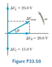
The voltage phasor diagram for a certain series RLC circuit is shown in Figure P33.59. The resistance of the circuit is 75.0 Ω, and the frequency is 60.0 Hz. Find (a) the maximum voltage ΔVmax, (b) the phase angle ϕ, (c) the maximum current, (d) the impedance
The voltage phasor diagram for a certain series RLC circuit is shown in Figure P33.59. The resistance of the circuit is 75.0 Ω, and the frequency is 60.0 Hz. Find (a) the maximum voltage ΔVmax, (b) the phase angle ϕ, (c) the maximum current, (d) the impedance

Ankit LalLv10
14 Dec 2020