ENGR2000 Lecture Notes - Lecture 10: Axial-Flow Pump, Centrifugal Pump, Centrifugal Force

2 Jul 2018
School
Department
Course
Professor

Prepared by Dr Hongwei Wu Chapter 10 – Page 1 of 14
2nd – Year Fluid Mechanics, Faculty of Engineering and Computing, Curtin University
ENGR2000: FLUID MECHANICS
For Second-Year Chemical, Civil and Mechanical Engineering
FLUID MECHANICS LECTURE NOTES
CHAPTER 10 PUMPS
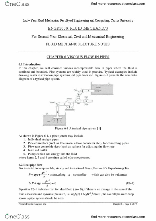
10.1 Introduction to fluid machines
A fluid machine is a device which adds (pump or compressor) energy into or removes
(turbine) energy from a fluid by dynamic interactions between the device and the fluid. There
are four categories of fluid machines: positive displacement (P.D.) machines, centrifugal fluid
machines, axial fluid machines and jet fluid machines.
A P.D. fluid machine works by allowing a fluid to flow into some enclosed cavity
from a low-pressure source, trap the fluid, and then force it out into a high-pressure
receiver by decreasing the volume of the cavity. Examples include a human heart and
a tyre pump (see Figure 10-1a).
A centrifugal fluid machine raises the pressure of a fluid by moving it outward in a
centrifugal force field, passing it radially across the impeller and giving it a high
kinetic energy and then converting that kinetic energy into fluid pressure energy.
Examples include centrifugal pumps for water delivery, as shown in Figure 10-1b.
For an axial-flow fluid machine (see Figure 10-1c), the fluid enters and leaves in the
direction of the axis of the rotor. Fluid passes through several rows of blades arranged
in an annulus and is successively accelerated by moving rows of blades, and then
slowed by a stator blade. The stator blade converts the kinetic energy imparted by the
rotating blade to pressure energy.
A jet fluid machine is used to convert kinetic energy into pressure energy, usually with
the objective of creating an overpressure at one point and a vacuum at another. For
example, ejectors, as shown in Figure 10-1d mix a high-velocity jet of driving fluid
with the fluid to be pumped, increasing the kinetic energy of the pumped fluid. The
kinetic energy is then converted to pressure energy.
We recall that in Chapter 6, the overall energy governing equation E6-2 (or E6-2a in head
form) of a pipe system includes a
work
P
term (or a
work
h
term in head form). The
work
P
term
is the pressure rise of the fluid from the pump in order to accommodate the changes in
elevation and dynamic energy, and overcome the pressure drop due to the friction loss in a
pipe system. Both pumps and compressors are fluid machines which add energy into the fluid.
The key difference is that pumps deal with incompressible fluid, e.g. water, while
compressors deal with compressible fluid, e.g. air.
Therefore, this chapter focuses mainly on pumps. We will learn knowledge on pump
performance curves, system curve, pump selection and dimensionless numbers which are
important to pumps.

Prepared by Dr Hongwei Wu Chapter 10 – Page 2 of 14
(a)
(b)
(c)
(d)
Figure 10-1 Type of Fluid machines: (a) positive displacement machines, such as a human
heart and a tyre pump [1]; (b) a centrifugal fluid machine, such as a centrifugal pump [1]; (c)
an axial-flow pump; (d) a jet fluid machine

Prepared by Dr Hongwei Wu Chapter 10 – Page 3 of 14
10.2 P.D pumps
A P.D. pump works by allowing a fluid to flow into some enclosed cavity from a low-
pressure source, trap the fluid, and then force it out into a high-pressure receiver by
decreasing the volume of the cavity.
As shown in Figure 10-2, the operation of a P.D. pump has the following steps:
a) The piston starts downward, creating a slight vacuum in the cylinder;
b) The pressure of the fluid in the inlet line is high enough relative to this vacuum to
force open the left-hand on-way valve, whose spring has been designed to le the valve
open under this slight pressure difference;
c) Fluid flows in during the entire downward movement of the piston;
d) The piston reaches the bottom of its stroke;
e) The piston then starts to upward. This raises the pressure in the cylinder higher than
the pressure in the inlet line, so the inlet valve is pulled shut by its spring.
f) Pressure continues to rise until it is higher than the pressure in the outlet line. If the
fluid were incompressible, this pressure rise would be instantaneous.
g) When the pressure in the cylinder is higher than the pressure in the outlet line, the one-
way outlet valve is forced open.
h) The piston pushes the fluid out into the outlet line.
i) The piston starts downward again; the spring closes the outlet valve, because the
pressure in the cylinder has fallen, and the cycle begins again.
Figure 10-2 Operations of a P.D. machine
The volumetric efficiency of a P.D. pump is defined as
D
I
VOL V
V
VolumentDisplaceme
VolumeIntake
where the displacement volume is the volume swept by the piston. In general, 100%
efficiency will not be achieved because of leakages in seals and valves, unswept volumes and
expansion of remaining fluid (for compressible fluids).
Figure 10-3 presents the performance curve of a typical P.D. pump. It can be seen that P.D.
pumps are constant-volumetric-flow-rate devices (at a fixed motor speed), maintaining almost
vertical characteristic curves, with slight deviations caused by leakages, which increase with
pressure. To increase flow rate of a fixed-geometry P.D. pump, one must increase the motor
speed. For example, a human heart is a P.D. pump (see Figure 10-1a). When we are running,
we need more blood supply so that increase the number of beats per minutes of heart.
Document Summary
2nd year fluid mechanics, faculty of engineering and computing, curtin university. A fluid machine is a device which adds (pump or compressor) energy into or removes (turbine) energy from a fluid by dynamic interactions between the device and the fluid. There are four categories of fluid machines: positive displacement (p. d. ) machines, centrifugal fluid machines, axial fluid machines and jet fluid machines. A p. d. fluid machine works by allowing a fluid to flow into some enclosed cavity from a low-pressure source, trap the fluid, and then force it out into a high-pressure receiver by decreasing the volume of the cavity. Examples include a human heart and a tyre pump (see figure 10-1a). Examples include centrifugal pumps for water delivery, as shown in figure 10-1b. For an axial-flow fluid machine (see figure 10-1c), the fluid enters and leaves in the direction of the axis of the rotor.