ENGR2000 Lecture Notes - Lecture 7: Globe Valve, European Route E73, Secondary Flow

2 Jul 2018
School
Department
Course
Professor

Prepared by Dr Hongwei Wu Chapter 7 – Page 1 of 17
2nd – Year Fluid Mechanics, Faculty of Engineering and Computing, Curtin University
ENGR2000: FLUID MECHANICS
For Second-Year Chemical, Civil and Mechanical Engineering
FLUID MECHANICS LECTURE NOTES
CHAPTER 7 PIPE COMPONENTS, PIPING SYSTEMS
7.1 Introduction
In Chapter 6, we learned that for real pipe flows, the pressure drop
L
P
across a pipe system
occurs due to the friction between the pipe system and the viscous fluid. The pressure drop
across a pipe system including the pressure drop in straight pipes (i.e., major loss, denoted as
majorL
P,
) and the pressure drop in various pipe components (i.e. minor loss, denoted as
orL
Pmin,
), as shown in E6-3.
orLmajorLL PPP min,,
The major loss in straight pipes can be calculated by E6-22 or E6-22a,
2
2
V
D
L
fP
or in head form
g
V
D
L
fh majorL 2
2
,
where the friction factor f can be obtained from the Moody chart (or calculated using formula
E6-26 for various regions of the chart) for both laminar and turbulent flows.
This chapter focuses mainly on minor loss and consists of three parts:
1. Calculation of minor loss of various pipe components including entrance and exit,
enlargements, contractions, bends, fittings such as tees, elbows, union, and valves.
2. Discussion on piping systems
3. Solutions of typical pipe flow problems with examples
Most of engineering problems deal with turbulent flows. It should be noted that the discussion
on minor loss in this chapter concerns turbulent flows (i.e. flows of large Reynolds numbers).
7.2 Loss coefficient,
L
K
7.2.1 Definition
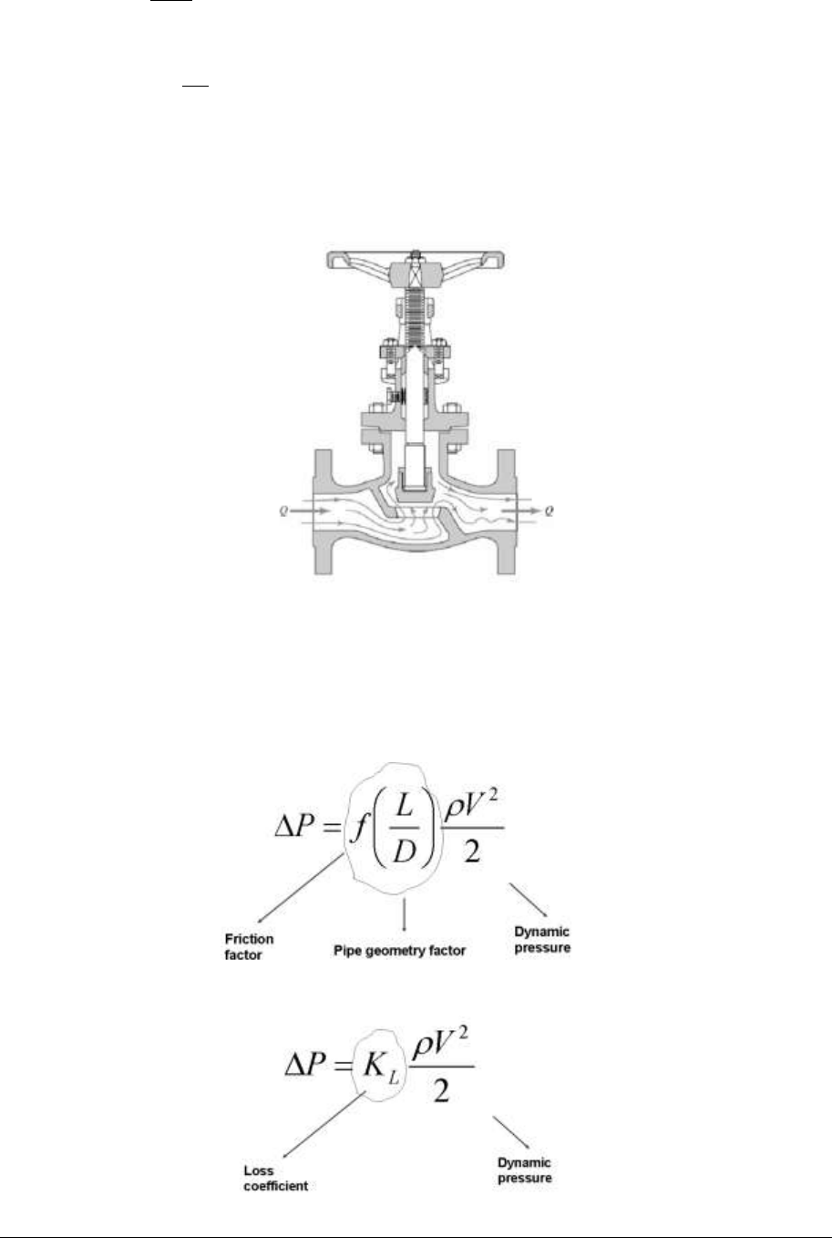
The flow patterns are generally very complex in a pipe component, such as flow through a
valve in Figure 7-1. Therefore, the analysis of pressure drop across a pipe component is very
complicated because the pressure drop is not only a function of the flow itself but also the
complex geometrics of the component.
To make it easy for engineers, minor loss across all pipe components can be expressed in a
generic form. The common method is to use a dimensionless loss coefficient, KL, which is
defined as
2
2
1V
P
KL
(E7-1)
find more resources at oneclass.com
find more resources at oneclass.com
Prepared by Dr Hongwei Wu Chapter 7 – Page 2 of 17
so that
2
2
V
KP L
(E7-2)
or in head form
g
V
Kh LorL2
2
min,
. (E7-2a)
The value of loss coefficient KL of each type of pipe components can be determined by
experimental investigations. The unified equations E7-2 and E7-2a for all pipe components
become convenient for the design and operation of practical pipe systems.
Figure 7-1 Flow through a valve [1]
7.2.2 Similarity between E6-22 and E7-2
If we closely examine E6-22 and E7-2, which are used to calculate major and minor loss,
respectively, we can see that the two equations are fundamentally similar.
For major loss in straight pipes:
For minor loss in pipe components:
find more resources at oneclass.com
find more resources at oneclass.com

Prepared by Dr Hongwei Wu Chapter 7 – Page 3 of 17
A key difference between the two equations is that the friction factor f and pipe geometry
factor (L/D) in the calculation of major loss have been accumulated into a single factor, loss
coefficient KL in the calculation of minor loss. This is because the geometry factor of straight
pipe is well-defined. While for a pipe component, the situation is more complex, 1) the
geometry can be very complex, as shown in Figure 7-1; and as a result of that, 2) the flow
pattern may also become very complex. Therefore, KL of a pipe component strongly depends
on the geometry of the component and normally can only be determined experimentally.
7.3 Loss coefficient
L
K
of various pipe components
7.3.1 Entrance and exit
Figure 7-2 illustrates the flow pattern and the distribution of static and dynamic pressure of a
pipe flow entering a sharp-edged pipe entrance.
(b)
Figure 7-2 Flow through a sharp-edged pipe entrance; a) flow pattern; b) static and dynamic
pressure distribution. The figure is from [1].
Let’s have a detailed analysis on entrance flow.
1. At point 1 far from the entrance, the fluid is stationary (V1 = 0) with static pressure P1.
2. Near the pipe entrance, the fluid starts to accelerate while it enters into the pipe
entrance from all directions. Because the flow direction is not entirely in the axial
direction, the radial inward velocity of the fluid leads to the formation of a narrowed
neck (also called the vena contracta) just downstream of the entrance.
3. As the flow is separated at the corner of the entrance, a collar of separated fluid
surrounds the neck, where the fluid velocity continues to accelerate (the fluid pressure
continued to decrease) until it reaches maximum velocity V2 at point 2.
find more resources at oneclass.com
find more resources at oneclass.com
Document Summary
2nd year fluid mechanics, faculty of engineering and computing, curtin university. In chapter 6, we learned that for real pipe flows, the pressure drop occurs due to the friction between the pipe system and the viscous fluid. The pressure drop across a pipe system including the pressure drop in straight pipes (i. e. , major loss, denoted as. ) and the pressure drop in various pipe components (i. e. minor loss, denoted as. The major loss in straight pipes can be calculated by e6-22 or e6-22a, fp. 2 g where the friction factor f can be obtained from the moody chart (or calculated using formula. E6-26 for various regions of the chart) for both laminar and turbulent flows. Most of engineering problems deal with turbulent flows. It should be noted that the discussion on minor loss in this chapter concerns turbulent flows (i. e. flows of large reynolds numbers).