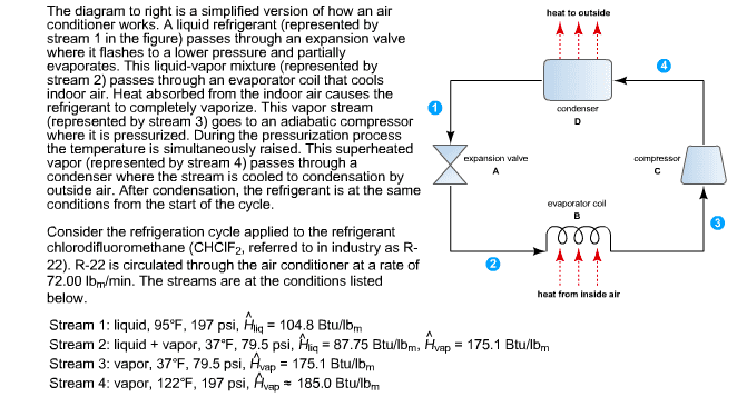
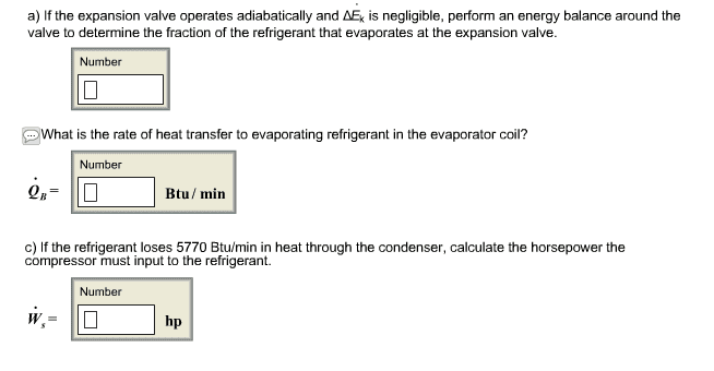
The diagram to right is a simplified version of how an air heat to outsid conditioner works. A liquid refrigerant (represented by stream 1 in the figure) passes through an expansion valve where it flashes to a lower pressure and partially evaporates. This liquid-vapor mixture represented by stream 2) passes through an evaporator coil that cools indoor air, Heat absorbed from the indoor air causes the refrigerant to completely vaporize. This vapor stream condenser (represented by stream 3) goes to an adiabatic compressor where it is pressurized. During the pressurization process the temperature is simultaneously raised. This superheated on valve compressor vapor (represented by stream 4) passes through a condenser where the stream is cooled to condensation by outside air. After condensation, the refrigerant is at the same conditions from the start of the cycle. evaporator coil Consider the refrigeration cycle applied to the refrigerant chlorodifluoromethane (CHCIF2, referred to in industry as R- A A A 22). R-22 is circulated through the air conditioner at a rate of 72.000 lbm/min. The streams are at the conditions listed heat from in e air below. Stream 1: liquid, 95 F, 197 psi, Hig 04.8 Btu/lb Stream 2: liquid vapor, 37 F, 79.5 psi, Hig 87.75 Btullbm, Hvap 175.1 Btu/Ibm Stream 3: vapor, 37 F, 79.5 psi, Hwap 175.1 Btu/lb Stream 4: vapor, 122°F, 197 psi, Hwap 185.0 Btu/lbm